The term “Radome,” derived from “Radar dome,” refers to a protective cover or enclosure designed to shield radar antennas from environmental factors. This article provides guidance on selecting the appropriate material and thickness for radar covers to ensure optimal performance.
Every cover affects the shape of the detection field and the maximum achievable distance. Despite radar’s ability to penetrate plastic and glass of any color, certain rules must be adhered to for effective design.
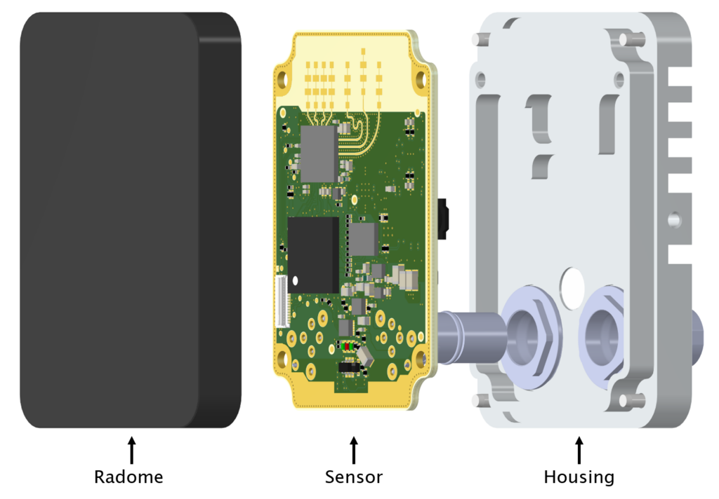
The cover of a radar sensor plays a pivotal role in its functionality, influencing sensitivity, radiated antenna pattern, and resistance to vibrations. Radome design is centered around reducing microwave reflection at the cover’s surface. Poor radome layout can lead to unintended sensitivity issues on the sensor’s reverse side. Additionally, the cover material can function as a lens, either focusing or dispersing radar waves. Hence, it is essential for the cover to maintain a consistent thickness within the transmission area to ensure optimal performance.
Radome design
General rule
A radome should be designed in order to minimize its influence on sensor sensitivity as well as on the field pattern of the radar antenna. Any reflection caused by the radome leads to a degradation of the sensor characteristics. For FMCW radars, proper radome design is even more important than for simple Doppler radars because reflections near the antenna cause strong feed through of the FM signal to the IF output.
Radome thickness
In order to get the optimal radome thickness, wavelength λm in the radome material plays a key role. Wavelength becomes shorter in a material than in free air, depending on the permittivity εr (also called dielectric constant). Our goal is to get a wavelength in the material of n*λm/2, so that the radome becomes nearly “transparent” for the microwave.
If you can use a material with εr of app. 1.0, the thickness doesn’t matter. Materials such as polystyrene and polyurethane foam have this property. They can also be placed directly on the antenna. Polyurethane foam can be sprayed very smoothly and thanks to the closed cells comes close to a plastic cover.
(1)
fc Transmitting frequency
c0 Speed of light (299’792’458 m/s)
λ0 Wavelength in free air
(2)
λm Wavelength in material
εr Relative permittivity of the material
(3)
Tm Optimal radome thickness
Suitable radome materials
Radome material must be dry and electrically isolating. Do not use coatings or paints containing metallic or carbon particles. Permittivity εr (dielectric constant) should be known in order to define optimal thickness according to formula (3). Low dissipation factor tanδ is important for low attenuation of the microwaves.
Permittivity εr and tanδ are mostly specified only up to 100MHz. At higher frequencies, εr values usually become slightly lower. Large tolerances apply to many materials. Try to get εr values from your supplier.
Distance antenna - radome
Optimal distance between antenna and radome allows minimizing the effects of reflections and antenna detuning caused by the radome. The following formula can be used as a rule of thumb for a patch antenna:
(4)
dm Minimal distance between antenna and radome
If the thickness of the radome has been selected correctly, the distance between the antenna and the radome can be smaller as dm, but the influences on the antenna diagram and the oscillator must be checked.
Vibration immunity
An imperfect radome reflects parts of the transmitted waves. As a radome can never be perfect, relative movements (vibrations) between antenna and radome will lead to large signal levels at the radar transceiver. These signals mostly look like normal Doppler signals caused by moving targets and can lead to malfunction of the sensor system.
Conclusion
- The patch antenna must under no circumstances be painted or covered with a plastic film. This changes the resonance frequency of the antenna and leads to a changed radiation.
- The cover must not be metallic and must not use plastic coatings that contain metal or carbon particles.
- Thickness of radome needs to be Tm or a multiple of Tm. Determine and manufacture the thickness of the cover with an accuracy of 0.1 mm.
- Distances below dm should be avoided while distances above dm are not as critical.
- Mechanical construction must prevent or at least damp relative movement between antenna and radome.