
Target audience: Radar System Engineers, Product Managers, Integrators
Reading time: approx. 5 minutes
Drones have become one of the most demanding targets for radar. They are small, slow, fly low and can appear from almost any direction. Compact 77 GHz radar is an attractive answer: it works day and night, in rain, fog and dust and modern automotive radar chips integrate transmitters, receivers and signal processing on a single device.
Out of the box, however, these chips are built for cars, not for drones. With their on-chip transmit power and noise figure, a small drone disappears after a few tens of metres. For electronica 2026, RFbeam developed the Active Antenna: a compact front end that turns a launcher-in-package radar chip into a counter-drone sensor with more than 200 m detection range and a beam that is steered electronically, without a gimbal.
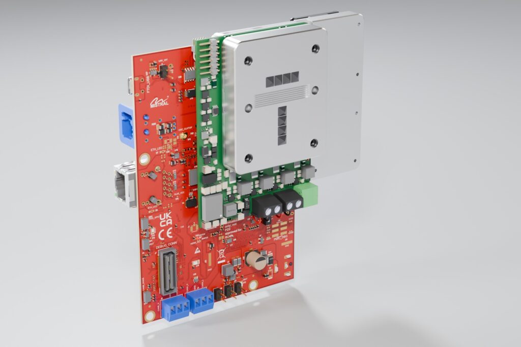
The Active Antenna mounted on the TI AWR2E44P evaluation module (3D render)
The challenge: small targets, short range
A small drone has a radar cross-section (RCS) of roughly −25 dBsm, about 30 cm². Because the received power falls with the fourth power of the distance, every doubling of the range costs 12 dB of signal-to-noise ratio. A typical automotive radar chip delivers about 13 dBm per transmitter and has a receiver noise figure of about 11 dB. With the same antennas and processing as described below, this limits the detection range for such a drone to about 70 m.
A narrow, high-gain antenna would help, but only in one direction. Classic systems therefore point the beam mechanically. A gimbal, however, adds size, weight, latency and wear – exactly what a compact sensor should avoid.
Amplifiers where they matter
The Active Antenna places a power amplifier (PA) behind every transmit horn and a low-noise amplifier (LNA) behind every receive horn. The amplifiers are bare-die MMICs, mounted on pedestals of the die carrier and wire-bonded directly to small waveguide-to-microstrip transitions. This keeps the lossy part of the RF path between amplifier and antenna as short as possible.
- Transmit power: 13 dBm → 30 dBm per channel (+17 dB)
- Receiver noise figure: 11 dB → 6 dB (−5 dB)
- 4 TX and 4 RX channels, each with its own amplifier
- Dielectric-filled horns with small lenses, optimised for 76–77 GHz
- TX-to-RX isolation above 53 dB thanks to choke grooves between the arrays
Together, the higher transmit power and the lower noise figure add 22 dB to the signal-to-noise ratio. In terms of range, this is a factor of 3.5.
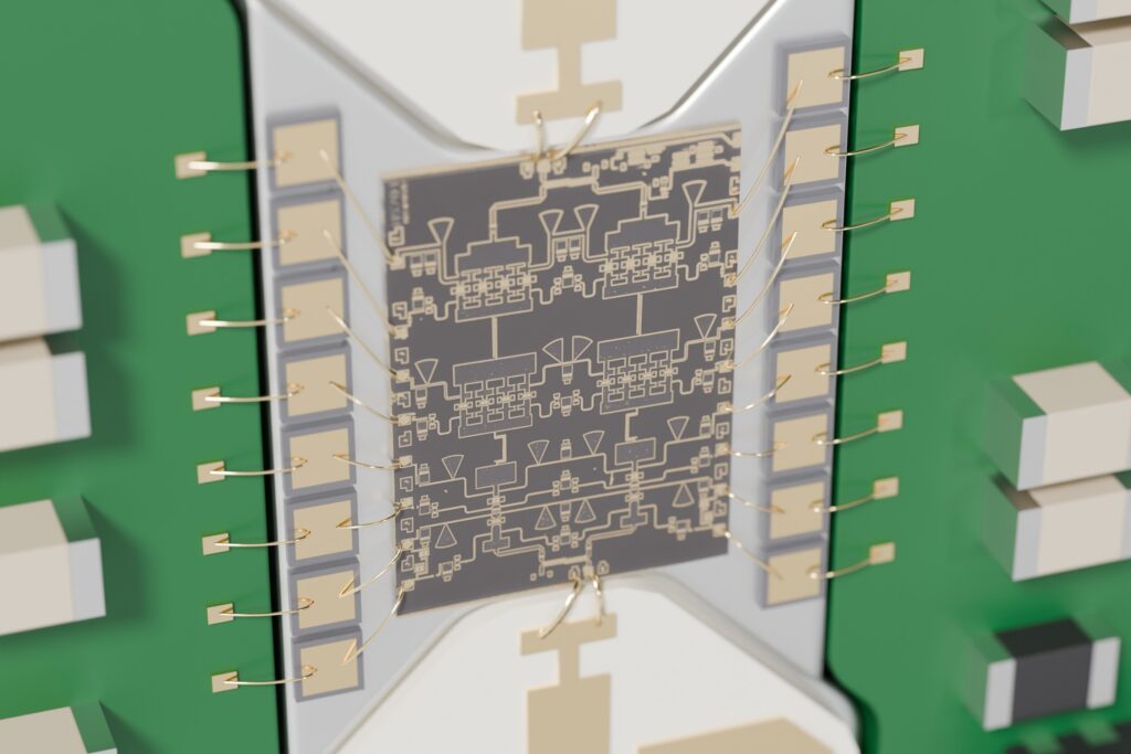
Bare-die power amplifier on its pedestal, bonded to silicon capacitors and to the waveguide transitions
Crossed fan beams instead of a gimbal
With only four channels per side, a classic pencil-beam array would need many more elements to cover a wide field of view. The Active Antenna uses crossed fan beams instead. The four transmit horns sit in a row and are phased in azimuth: they form a beam that is narrow in azimuth and wide in elevation. The four receive horns sit in a column and are combined digitally in elevation: a beam that is narrow in elevation and wide in azimuth.
The radar sees the product of both patterns – a pencil beam with 35.5 dB two-way gain on boresight (simulated). It is placed anywhere in a 50° × 50° field of view by setting the transmit phases and the receive beamforming weights, giving 4 × 4 independent beam positions. No part of the sensor moves.
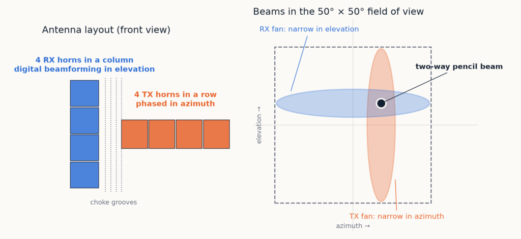
Crossed fan beams: the TX row forms a vertical fan, the RX column a horizontal fan; together they form a steerable pencil beam
Inside the module
The Active Antenna is built as a stack of five layers and measures 81 × 77 × 32 mm, including cooling:
- Antenna block: 4 TX and 4 RX horns, filled with dielectric and closed by small lenses
- Waveguide routing layer: connects the launcher outputs of the radar chip to the horns
- Die carrier: PA and LNA dies, waveguide-to-microstrip transitions and the bias board
- Base plate: mechanical and waveguide interface to the launcher-in-package chip
- Two 30 mm fans for the amplifiers
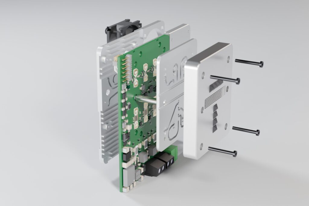
Exploded view: fans, base plate, die carrier with PCB and bare dies, waveguide routing layer and antenna block
How far can it see?
We calculated the detection range with the radar equation, using the simulated two-way gain of the crossed fan beams with both beams steered onto the target. The chirp uses 250 MHz bandwidth, 1024 samples at 30 MHz and a 20 ms frame (585 chirps, coherently integrated). A detection requires an SNR of 12 dB, and 9.1 dB of feed, antenna and processing losses are included.
Target direction | Active Antenna | Chip alone |
Boresight | 238 m | 68 m |
Edge of the field of view, azimuth ±25° | 161 m | 46 m |
Edge of the field of view, elevation ±25° | 155 m | 44 m |
Corner of the field of view (±25° / ±25°) | 107 m | 30 m |
Above 200 m is reached in the centre of the field of view, and even the corners keep more than 100 m. All values are calculated for a steady −25 dBsm target; a strongly fluctuating target needs more SNR and reduces these ranges accordingly.
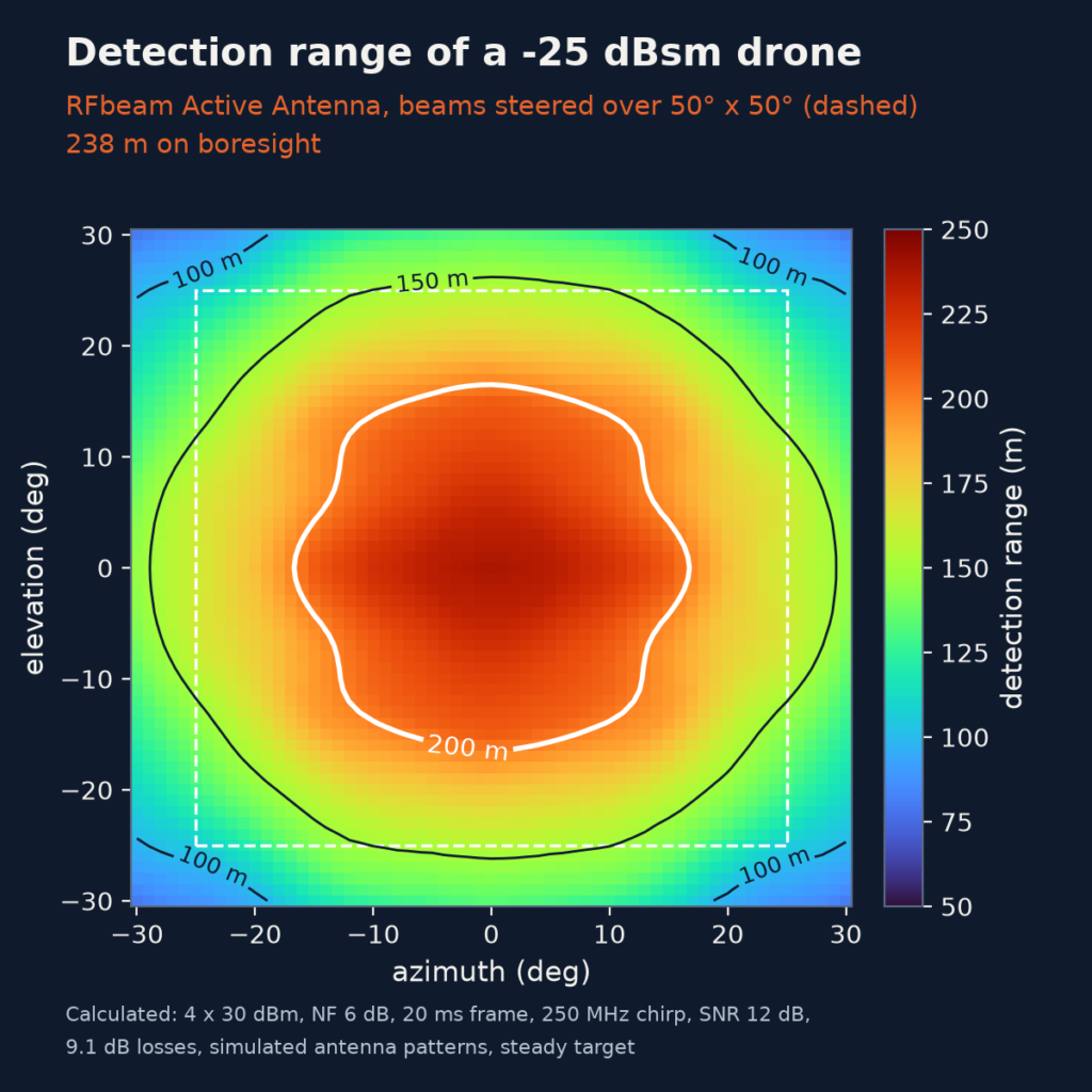
Calculated detection range of a −25 dBsm drone over the field of view
Demonstrated on the TI AWR2E44P
Our demonstrator is built on the Texas Instruments AWR2E44P evaluation module (AWR2E44PEVM). The AWR2E44P provides its transmit and receive signals through launchers in the package, which feed a waveguide antenna through openings in the PCB. The Active Antenna replaces the module’s 3D antenna and uses the existing interface:
- the same mounting holes, with two dowel pins and three M2 screws
- the 8 launcher ports, reaching the module through the existing slots in the PCB
- fans placed beyond the board edge, like the overhang of the original antenna
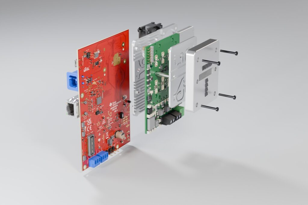
The Active Antenna replaces the 3D antenna of the AWR2E44PEVM and uses its existing interface
A concept that adapts
The Active Antenna is a design concept rather than a fixed catalogue product. The waveguide routing layer decouples the horn layout from the launcher positions of the chip, so the same architecture can be adapted to other launcher-in-package radar chips. Horns, arrays and lenses can be tuned for a different field of view or gain, and the mechanics and cooling can follow the customer’s housing.
See it at electronica 2026
We will show the Active Antenna at electronica 2026 in Munich, 10–13 November 2026, at the RFbeam booth (Hall B4, booth 220). The demonstrator can also be seen at the Texas Instruments booth.
Conclusion
Automotive radar chips bring a complete 77 GHz radar onto a single device, but their range is not enough for small drones. By adding a power amplifier and a low-noise amplifier to every channel and steering crossed fan beams electronically, the Active Antenna extends the calculated detection range of a −25 dBsm drone to 238 m on boresight – in a compact module and without moving parts.
Links
Planning a long-range or counter-drone radar project? Our Field Application Engineers support you from the first concept to series production. Contact us at office@rfbeam.ch.