The detection range of a radar sensor is one of its most critical performance parameters. It defines the maximum distance at which an object can be reliably detected. The physical principles behind detection range can be precisely described using the radar equation. In this article, we explain the main influencing factors and illustrate with practical examples how system parameters affect detection range.
The Radar Equation
For monostatic radar systems — where transmitter and receiver are co-located — the simplified radar equation is:
$$P_r = \frac{P_t \cdot G_t \cdot G_r \cdot \lambda^2 \cdot \sigma}{(4 \pi)^3 \cdot R^4 \cdot L}$$
where:
$P_r$: received power [W]
$P_t$: transmitted power [W]
$G_t,G_r$: transmit and receive antenna gains [linear]
$\lambda$: wavelength [m]
$\sigma$: radar cross section (RCS) of the target [m²]
$R$: distance to target [m]
$L$: system losses (e.g., rain) [linear]
Factors Influencing Detection Range
Derived from the radar equation, the primary parameters affecting detection range are:
- Transmit power $P_t$: Higher output power extends the range
- Antenna gains $G_t,G_r$: Narrow, high-gain antenna beams increase range
- Wavelength $\lambda$: Longer wavelengths (lower frequencies) favour better range for the same RCS
- Target radar cross section $\sigma$: Larger or highly reflective objects increase detection range
- System losses $L$: Any losses between transmission and reception reduce effective range
Additionally, receiver noise and signal processing (SNR required for detection) play critical roles that are not directly visible in the classical form of the radar equation.
Transmit Power
Limitations are given here by the RF frontend used in the sensor itself. However, a more crucial limitation is imposed by regulations, which limit the allowed radiated power of a radar sensor (for example, +20dBm EIRP for the 24GHz/60GHz band in Europe). This means that the combination of transmit power and TX antenna gain must remain below a defined limit depending on the frequency band and region where the sensor is planned to be used.
Antenna Gains
A higher antenna gain helps to improve the detection range but can only be achieved by using more narrow antennas. This results in a smaller Field of View (FoV) and a larger antenna size. Additionally, especially the TX antenna gain $G_t$ can also be limited by regulations, as mentioned above. The RX antenna is not limited by regulations, but the required FoV for detection and the size of the sensor are the typical limiting factors here.
Wavelength
Higher frequencies correspond to shorter wavelengths, which have a direct impact on the free-space path loss (FSPL). As the frequency increases, the FSPL also increases, meaning that signals at higher frequencies experience greater attenuation over the same distance. This is why 24 GHz radar sensors are generally better suited for long-range applications than 60 GHz sensors, which, despite offering advantages like higher resolution and smaller antennas, experience higher free-space path loss and thus shorter effective detection ranges.
Radar Cross Section
The Radar Cross Section (RCS) of an object defines how detectable it is by radar. It quantifies the amount of radar power scattered back to the receiver and is dependent on the target’s size, shape, material and orientation relative to the radar.
RCS is typically expressed in square meters (m²), but for practical radar applications it is usually represented in dBsm (decibels relative to 1 m²).
Table 1: Typical RCS values for different objects
Object | RCS (m2) | RCS (dBsm) |
Pedestrian | 0.1 .. 1 | -10 .. 0 |
Bicycle | 0.4 .. 1 | -4 .. 0 |
Motorcycle | 1 .. 5 | 0 .. 7 |
Car | 10 .. 50 | 10 .. 17 |
Truck | 100 .. 200 | 20 .. 23 |
Larger and more reflective objects, like cars and trucks, have a higher RCS, making them easier to detect. Conversely, smaller objects like bicycles and pedestrians have a lower RCS and are harder to detect at longer ranges.
System losses
System losses include environmental factors like atmospheric absorption, rain, fog and other conditions, as well as component-related losses in the system itself. These factors collectively reduce the radar’s effective range.
Impact of Attenuation on Detection Range
Since $P_r \sim 1/R^4$, a signal attenuation $D$ in dB reduces the detection range according to:
$$R_{new} = R_{original} \cdot 10^{-\frac{D}{40}}$$
This formula applies to monostatic radar systems, where the transmitted signal travels to the target and back — meaning the total path loss is squared and thus the dB-based reduction is divided by 40 when translated into range.
Example
A 12 dB reduction in received signal results in app. 0.5, what means half the detection distance.
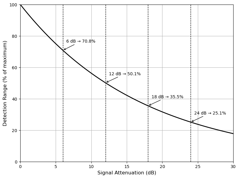
Figure 1: Relation between signal attenuation and detection range
Field of View Specification
At RFbeam, the Field of View (FoV) of radar sensors is specified at either the -6 dB or -12 dB points of the system diagram (Combined TX/RX characteristic).
Due to the reduced antenna gain at the edges of the FoV, the maximum detection range decreases:
- At the -6 dB point, detection range is about 71% of the range at boresight
- At the -12 dB point, detection range is about 50% of the range at boresight
Thus, targets located near the edge of the specified FoV are detected at shorter ranges compared to targets directly ahead.
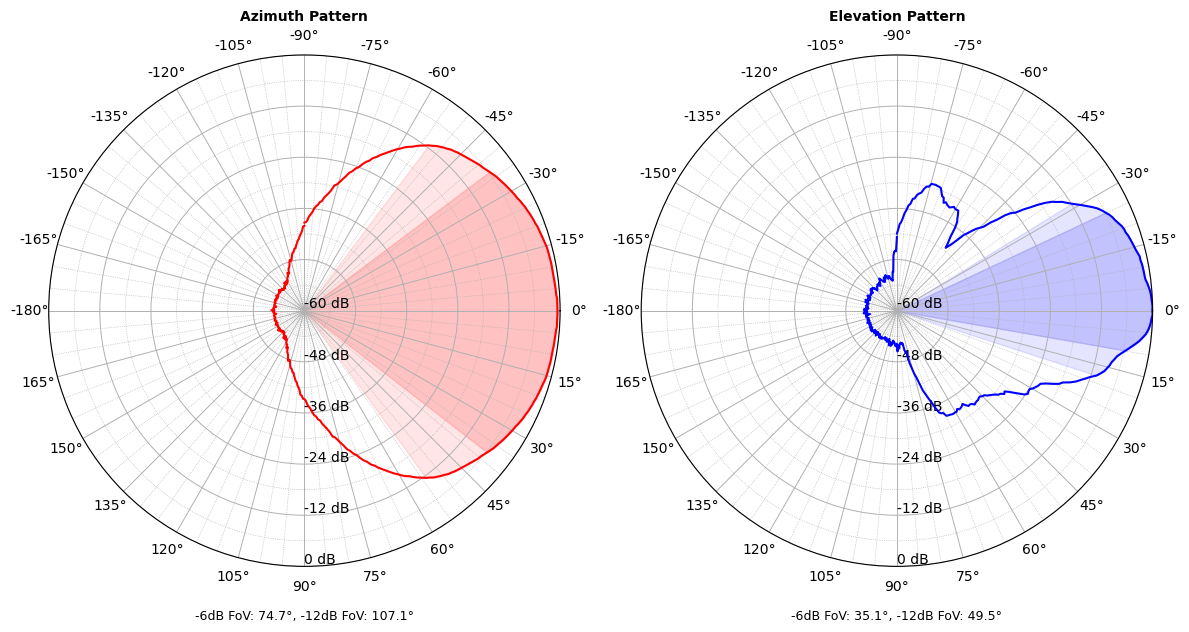
Figure 2: Example antenna pattern showing -6dB and -12dB FoV areas
If a car, for example, can be detected at boresight (0°) up to 100 meters, it can be seen at the -6dB point edges (±37.4°) up to approximately 71 meters and at the 12 dB edges (±54°) up to approximately 50 meters.
Further, detection at higher angles will still be possible but with reduced distance. If we take a look at the -24 dB points, we can see that the FoV will be approximately ±70° in azimuth, meaning that in this example, a car can be still seen up to approximately 25 meters in this wider field.
Practical Examples
Example 1: Environmental Influence
Under heavy rain or snow, atmospheric attenuation increases. A sensor achieving 100 meters in clear weather may see its range reduced to 60–70 meters.
Example 2: Target Size Variation
A vehicle (e.g., 10 m² RCS) can be detected from 200 meters, whereas a pedestrian (e.g., 1 m² RCS) may only be detected from about 70 meters.
Example 3: Antenna Optimization
Improving the antenna gain can significantly impact radar performance. For example, increasing antenna gain by 3 dB, while keeping all other parameters constant, theoretically increases detection range by approximately 19%. This is because a 3 dB increase in antenna gain doubles the transmitted or received power, which in turn increases the detection range by the square root of that increase.
Conclusion
The detection range of a radar system is the result of multiple interacting technical parameters. Key factors such as transmit power, antenna gain, wavelength, Radar Cross Section (RCS) and system losses all play significant roles in determining how far a radar sensor can detect an object. Additionally, environmental influences like rain, fog and atmospheric attenuation, further impact the effective detection range.
Furthermore, the Field of View (FoV) of a radar system has a direct effect on the range performance, as targets at the edges of the FoV are detected at shorter ranges compared to those at the center. Understanding the relationships between these factors is crucial for optimizing radar systems and ensuring their effectiveness in real-world applications.
RFbeam offers comprehensive support for selecting and customizing radar sensors tailored to meet your specific needs, ensuring optimal performance for a wide range of applications.